|
1. Introduction It is well known that repeated unsteady motions of walls of a container filled with a highly viscous fluid or unsteady motions of solid bodies immersed in the fluid can produce a chaotic mixing in the fluid, which is called "Lagrangian turbulence" (Ottino, 1989a,b). It can be visualized by adding some dyes with the same viscosity beforehand. The main interest in this phenomenon has been the mechanism of chaotic behavior as a result of accumulation of dye displacements. In fact, resultant dye patterns are similar to the Poincare maps characteristic of chaotic behavior of dynamical systems. On the other hand, this phenomenon has been attracting fluid-dynamists because of the beauty of resulting patterns. This fact may suggest that this phenomenon can be applied as a new method of creating artworks. The term "rheo" in the title means a flow, and "rheo-art" should mean an art produced by application of the fluid dynamics. Since there are a lot of flow patterns in the nature, there should be also many kinds of rheo-art. However, in this paper we confine ourselves to the viscous mixing noted above, simply because it is relatively easy to simulate this flow.
The present author has recently made an attempt to apply 2D (two-dimensional) chaotic
mixing to produce attractive patterns by numerical method (Takaki
& Tomioka, 1997). In thepresent paper this attempt is applied
to other 2D configurations of cylinders and also extended to a 3D configuration.
Furthermore, it is tried to make up solid models form the computed results
with a help of a sculpture artist, Mr. Y. Nakatsugawa. The purpose
of this paper is to present results of these studies, and to make a fundamental
discussion on similarities and differences between art and science.
2. Method of Computation
The 2D
chaotic mixing is produced by a method similar to that first introduced
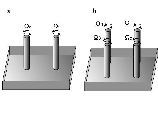
by Aref (1984). In his computation two circular cylinders were set
vertically in a container filled with a viscous fluid (see Fig. 1a).
They are rotated around their axes very slowly by certain angles in turn,
so that only one cylinder is rotated while the oher is at rest. The
fluid around a rotating cylinder moves according to the theory of
slow flows, i.e. the velocity induced by the rotation is inversely
proportional to the distance from the cylinder axis.
In the present paper cases with two and four equal cylinders are tried (see Figs.
1a and 1b). Rotation angles of cylinders and the order of their motions
can be chosen arbitrarily. But, a common rotation angle is chosen
and the sense of rotation of each cylinder and the order of motions are
left arbitrary.
When a flow field is produced by rotation of one cylinder, the flow is modified
by existence of other rest cylinders because the fluid should go round
these objects. However, in this study their effects are neglected
in order to simplify the computation of fluid motion. It is allowed
when mutual distances between cylinders are much larger than
their diameter.
In a typical case of two cylinders, which are denoted with surfices 1 and 2,
respectively (Fig. 1a), they are rotated by angles in an order,
This expression show that the
following four processes constitute one step of operation: cylinder 1 is
rotated clockwise by 180�, cylinder 2 clockwise by 180�,
cylinder 1 anti-clockwise by 180�, then cylinder 2 anti-clockwise by 180�.
Note that the clockwise rotation is denoted by a positive angle.
This operation is repeated by arbitrary number of steps so long as computing
time is available.
In the case with four cylinders a similar expression of processes is employed
(Fig. 1b). In this case one step of processes is expressed as
At the beginning several spots of dyes with many colors are placed on the fluid
surface, where the viscosity of the dye is assumed equal to that of the
fluid, so that the dyes move according to the same rule as for the fluid.
Number, shapes, sizes and positions of initial dye spots vcan be given
also arbitrarily. But, by try-and-error one may find that most interesting
patterns will be obtained when several spots are placed within the central
region, so that initial spots are surrounded by cylinders. In the
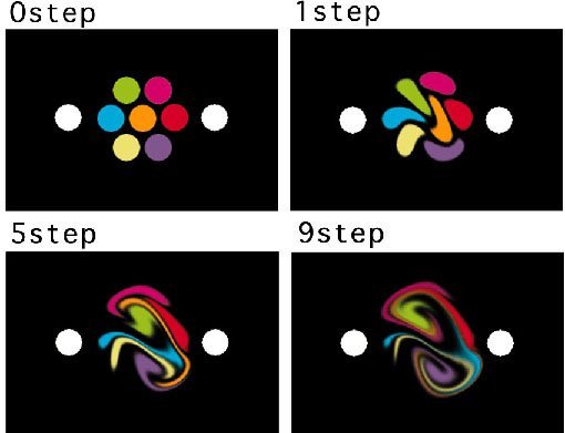
first case with two cylinders seven dye spots are placed in hexagonal configuration
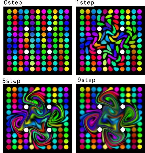
(Fig. 3). In the case of four cylinders a lot of spots are
placed in square grid configuration (Fig. 4).
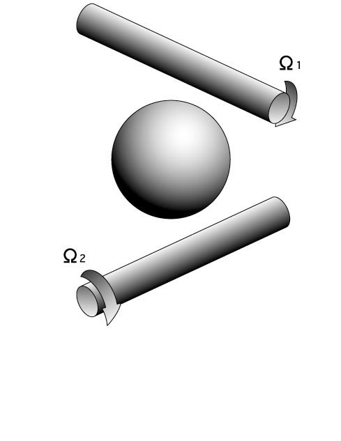
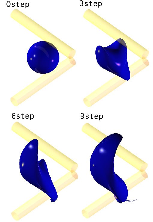
Similar processes are made in the case of 3D viscous mixing. In this study
two equal cylinders are set perpendicularly in a deep container of a viscous
fluid with their axes apart, and one spherical dye is placed between the
two cylinders as an initial condition. Each cylinder is rotated one
after another by 180� always in the same direction, i.e.
The fluid is assumed to
go round the rotating cylinder in a plane perpendicular to the cylinder
axis, where the effect of the other cylinder is neglected as mentioned
above.
It is worth noting that it must be also interesting to undertake real experiments to produce mixing patterns, although there may arise some difficulties, for example in suppressing dye diffusion and initial fluctuation of dye inputs. In addition many other cases with various cylinder arrangements (or with other solid objects) and initial dye patterns could be tried to see whether they lead to attractive patterns. Readers are suggested to try themselves. At least the 2D mixing is easy and anyone can begin immediately, if he(she) has a personal computer.
3. Results of 2D cases
Fig. 3 shows an initial dye pattern and its deformations after several steps in
the case of two cylinders due to the four-process operation (Eq. (1)).
Readers might agree that delicate and beautiful patterns are obtained.
The resulting patterns have two complicated swirling centers, each of which
by close observation is seen to be a mixture of rotations of opposite senses.
The whole pattern does not have a symmetry inspite of the symmetrical configuration
of cylinders. It is owing without doubt to the asymmetry of operation,
i.e.
the right cylinder is rotated first. This coexistence of large scale
order and asymmetry seems to give an attractiveness to these patterns.
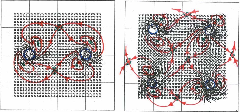
The displacement
vector field corresponding to one step of four-process operation is shown
in Fig. 5 (left). In this figure the angle of rotation is increased
to 360�
so that fluid dispalenments are seen more clearly.
Some trajecroties are also drawn on the map. The complicated swirling
centers are located near both to the hyperbolic point (saddle point) and
the elliptic point (vortex) in the map. It is in accordance with
the common fact established in the chaos dynamics. It is interesting
to point out that the swirling centers are nearer to the hyperbolic points
(not the elliptic points) inspite of their swirling nature!
Resulting patterns in the four-cylinder case are shown in Fig. 4. They have
4-fold symmetries corresponding to the square configuration of cylinders,
but the symmetry is broken owing to the asymmetry of operation, as in the
two-cylinder case. The fluid displacement map, shown in Fig. 5 (right),
is much complicated, but one can recognize six hyperbolic points and eight
elliptic points. The two hyperbolic centers within the cylinder square
seem to contribute much in formation of highly chaotic mixture at the center.
The hyperbilic points located out of the cylinder square are located near
to the outer swirling centers as in the two-cylinder case.
4. Results of 3D cases
Some of dye patterns up to the 9th step in the 3D case are shown in Fig. 6.
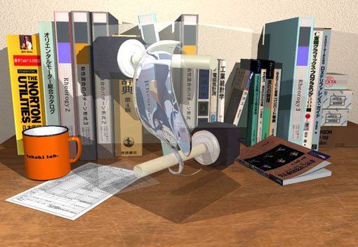
The 9th pattern is displayed once more in Fig. 6(below) by the use of a
software of ray-tracing. As is seen from these patterns, the
dye continues to be wound to the two cylinders and aquires a long thin
tail at one end. Appearance of a thin tail is observed also in 2D
cases and not so surprising, although it is more complicated in 3D cases.
As is mentioned in Sec.1, this 3D simulation can
be applied to art creation, i.e.
a sculpture. A shape constructed from the 3D simulation is called
a "scientific model", because it is also a scientific result. A scientific
model was constructed to a solid model fairly faithfully with a help of
a sculpture artist, Y. Nakatsugawa. A more precise discussion will
be given on the meaning of "scientific" in the next section in terms of
"repeatability".
Along with this scientific model the present author asked the artist to create
a solid model with a new shape according to his inspiration from this model,
which is called an "artificial model" (see Fig. 7). The term "artificial"
means that the model reflects the artist's desire and concept but the repeatability
is not expected, as is usual in hand works.
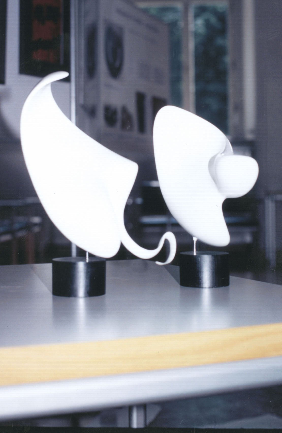
There are some clear differences between these two models. First, the artificial
model lacks the thin tail. Second, the surface of the artificial
model has a spherically concave part, which lacks in the scientific model.
Third, the thickness distributions are different (not apparent from this
picture), so that it tends to change monotonically in the scientific model,
while the artificial model has wavy distribution. In other words
the scientific model has a thickness distribution like that of a knife,
while the shape of the artificial model is more biological. These
characteristics of the artificial model may reflect the artist's ideas. When
the present author showed these models to participants of a conference
(Takaki & Tomioka, 1997), most of them preferred the artificial model
to the scientific model, except one who is an engineer.
Fig. 7
Solid models produced by Y. Nakatsugawa. left: faithful
copy of the 9th step
(scientific model), right: a shape created by Y. Nakatsugawa (artificial
model).
5. Discussions
Results shown above would suggest that the simulation of chaotic mixing of a viscous
fluid can provide a new method of art production. Especially, the
2D simulation is made by the use of a conventional softwares and
is open to anyone who can use a personal computer. On the other hand,
production of scuptures from computer simulation is still difficult at
present for general people, because they must be engaged in computer programming
and must have partners to help them in making solid models from computer
data.
As for the solid model production from computed data there is a possibility to
utilize a facility for photo-solidifying reaction, so that computed surface
shapes are automatically reproduced to plastic models. The present
author is considering to try this method in near future.
This author has been using the term "art" too easily without discussing its
meaning. Here, some discussions are given on the common features
and differences of science and art on the basis of the author's experiences
during activity of this work. This problem can be treated from variety
of aspects and discusser's standpoints, but the present author would like
to put a stress on the following points.
Science and art are similar to each other in:
Their objects are to create
new knowledges (new forms), and originalities are important.
Their results should be
presented to public and new human communications are triggered
therewith.
Utilities of results are
expected by society, but scientists (artists) prefer to be free from the
utilies.
On the other hand, science and art are different in the
processes of creations as listed below:
In science the repeatability is important,
i.e. if the same conditions are given, the same results
must be obtained. Therefore, especially in experimental works,
artificial control of phenomena during an experimental run is avoided.
In art, on the other hand, the human sensitivity to the artwork is important
and repeatability is neglected, so that artificial control to improve the
resullts is continuously made during production and no equivalent pieces
of works are producued even by the same artist.
The mental processes occurring
in scientists and artists are just opposite to each other.
The science is an activity to extract natural laws from real phenomena,
which is to convert form to concept. On the other hand,
the art is to produce real forms out of artist's imaginations, which is
to convert concept to form.
These two differences look very much critical, hence science and art have been supposed
to belong to different categories of human activities. However, in
spite of these differences they have a close relation as ointed out above.
Now, as for the rheo-art proposed here, it is considered to belong to the category
of science, because the process of production is that of science.
In fact, initial conditions are given and algorithms of dye deformations
are determined first, then the later processes proceed automatically without
any artificial manipulation. There is still a room for the human
sensitivity to play a role, by choosing better results from scientific
results and adjusting initial conditions or parameters. This
way of creation is called here "rheo-art".
However, we need an appropriate facility in order to display results of rheo-art.
In the present work we have no problem with the 2D cases, because convetional
color printers are enough for that purpose. On the other hand, displays
of 3D works are not straight forward. In fact the present author
needed a cooperation with a scuplture artist to make solid objects.
Is the light-solodification technique becomes more popular, this problem
will be solved. The present author is considering to try this way
in future.
It is hoped that the rheo-art will become possible by much easier method so that
many people can use it. A true art should be based on simple technologies;
Picasso used the same tools which we are using now.
Acknowledgements
The present author would like to express his cordial thanks to Mr. S. Tomioka for his
long term helps in computer simulations and to Mr. F. Nakatsugawa for his
kind efforts to make up solid objects from computed data. The present
work would not have been completed without their helps.
References
Aref, H., 1984, Stirring by chaotic advection, J. Fluid Mech. 143, 1-21.
Ottino, J.M., 1989a, The Kinematics of Mixing, Cambridge Univ. Press.
Ottino, J.M., 1989b, The mixing of fluids, Scientific American, January, 40-49.
Takaki, R., 1994, Proposal of a new kind of art "Rheo-art",
FORMA, 9,
203-208.
Takaki, R. and Tomioka, S., 1997, Mixing of viscous fluid
and its application to art,
Abstracts of 2nd Int. Conf. on Flow Interaction, Berlin, 1997,
3-5.
|